String Cable Runs: Voltage Drop in Practice
Voltage drop on a string is not a mystery; it is current multiplied by the resistance of the copper on the way out and back, and the only lever most projects can still move is the cross-section. KUKA CABLE publishes the construction of each size rather than a current table: 56 strands of 0.29 mm at 4 mm², 84 at 6 mm² and 142 at 10 mm², and the same solar dc cable pages give the diameter and weight per metre that go with each one.
Key takeaways
- Drop is set by current, run length and conductor, so at a fixed current and length it falls roughly in proportion to cross-section - 10 mm² carries about 2.5 times the copper of 4 mm² (my own arithmetic).
- Published construction: 4 mm² is 56 strands of 0.29 mm, 6 mm² is 84 strands and 10 mm² is 142 strands, all class 5 flexible tinned copper to IEC 60228.
- Rated voltage is DC 1.8/1.8 kV, with a 6.5 kV AC test at 50 Hz held for 5 minutes on the finished cable and a 10 kV spark test during production.
- Current-carrying tables and per-metre resistance values are not published on the site, so a design that depends on them has to ask the manufacturer for the type test report.
What sets the drop on a string
The familiar relationship is current multiplied by resistance, counted twice because the current leaves the array and returns to it. Resistance, in turn, depends on the conductor area and on how the metal is arranged inside it: a stranded class 5 conductor has slightly more resistance than its nominal area suggests, which is one reason published strand data is more useful to a designer than a marketing description of flexible copper.
On a real roof the number that matters is the length on a drawing. A string that runs 30 m from the last module to the inverter and another 30 m back is 60 m of conductor, and the drop scales with that figure, with the current, and inversely with the cross-section. The manufacturer's top-ten list of PV cable tests names conductor resistance as the first item, which is a fair sign of where the measurement work happens.
Cross-section is the lever you still have
Once the module layout is fixed and the string is wired in series, the current cannot be reduced and the run cannot usually be shortened. What remains is the size of the conductor. Going from 4 mm² to 6 mm² multiplies the metal by 1.5 and going to 10 mm² multiplies it by 2.5, so the drop at the same current and length falls in roughly the same proportion, which is my own arithmetic on the published cross-sections rather than a manufacturer's claim.
That relationship explains why the commonly used sizes for PV work are 4 mm², 6 mm² and 10 mm². It also explains why the strand counts in the published table rise faster than the nominal area: 142 strands at 10 mm² against 56 at 4 mm² is a factor of 2.54 on an area factor of 2.5, which is my own calculation from the published figures and reflects how the strand diameter stays constant across the range.
Length, joints and the rest of the circuit
A drop calculation that stops at the cable ignores the places where the resistance is not published: connector interfaces, combiner terminals and any field-made joint. The published test list includes cable connectivity alongside conductor resistance, insulation resistance and dielectric strength, which is the manufacturer saying that the termination belongs to the same question as the conductor.
Practically, that means a string that measures well on paper can still show a wide spread between strings on site. The cure is the same: keep the number of interfaces low, use the connectors made for the cable, and measure the drop per string after commissioning rather than only on the design sheet.
What the manufacturer publishes, and what it does not
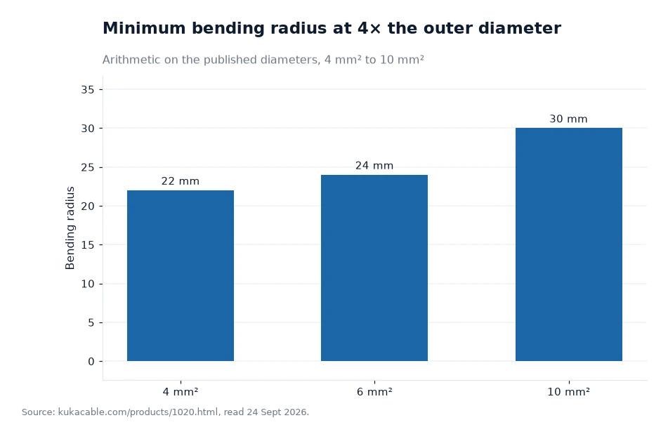
Published values cover most of a mechanical and insulation check: rated DC 1.8/1.8 kV, a 10 kV spark test during production, a 6.5 kV AC test at 50 Hz for 5 minutes on the finished cable, a minimum bend radius of 4 times the outer diameter, an ambient range of -40 °C to +90 °C, +120 °C over 20,000 hours and +250 °C for 5 seconds in short circuit, with a service life stated as 25 years or more.
What is missing is the electrical sizing data: there is no per-metre resistance table and no current-carrying table on the site. The manufacturer states that its solar cables are certified by TUV, IEC, CPR and others, and describes TUV certification as the starting point, so the sensible request is the type test report for the size being used, listed on the certificates page. A designer who needs resistance figures for a drop calculation should obtain them from that report rather than from a general figure on a similar cable.
| Nominal cross-section | Conductor construction | Nominal overall diameter | Relative drop at equal current and length |
|---|---|---|---|
| 4 mm² | 56 strands of 0.29 mm | 5.5 mm | Reference, 100 |
| 6 mm² | 84 strands of 0.29 mm | 6.0 mm | About 67 |
| 10 mm² | 142 strands of 0.29 mm | 7.5 mm | About 40 |
| 16 mm² | 238 strands of 0.29 mm | 8.8 mm | About 25 |
| 25 mm² | 375 strands of 0.29 mm | 11.0 mm | About 16 |
Worked example
Suppose a design shows a 3.0% drop on a run built in 4 mm². At the same current and the same length, moving to 10 mm² would take it to about 1.2%, because the published cross-sections sit in a ratio of 4 to 10 and the drop falls with the cross-section (3.0 multiplied by 0.4 equals 1.2; my own arithmetic, assuming no change in current, length or joint count and ignoring the small effect of stranding). The same move at 6 mm² gives about 2.0% (3.0 multiplied by 0.667; my own arithmetic).
The cost of that move is weight rather than voltage. The published weights are 59 g/m at 4 mm², 78 g/m at 6 mm² and 130 g/m at 10 mm², so a 1,000 m order grows from 59 kg to 130 kg of cable when the design changes size (my own multiplication of the published figures, assuming the weight excludes the drum). A designer balancing drop against handling should ask for both numbers before the layout is frozen.
Frequently asked questions
How do you reduce voltage drop on a long string run?
Raise the cross-section, because the run length and the string current are usually fixed by the array layout. On the published cross-sections, 10 mm² carries two and a half times the copper of 4 mm², so at equal current and length the drop falls to about 40% of the 4 mm² figure (my own arithmetic). Then ask the manufacturer for the type test report, since the site publishes strand counts and diameters but no per-metre resistance or current-carrying tables.
Does the manufacturer publish current ratings or resistance values for its solar cable?
No. The published material covers construction, diameter, weight per metre and the insulation values - rated DC 1.8/1.8 kV, a 6.5 kV AC test for 5 minutes and a 10 kV spark test in production - while conductor resistance appears only as a named test rather than as a table of figures. A project that needs resistance or current data for a drop calculation should request it from the product consultant together with the type test report.
Two values to check on the datasheet
Before a string layout is signed off, find the conductor construction for the size in use and the conductor resistance figure from the type test report, then repeat the drop calculation with the real length rather than the drawn one. Ask the consultant which certificate applies to the batch, because a design that leans on a standard needs the paper that matches it. The published sizes start at 1.5 mm² and run to 240 mm², so there is usually a step available when the arithmetic says the run is too long for the size on the drawing.
Attribution: this voltage-drop walkthrough uses the manufacturer's published web figures and nothing else, and the cable data behind it was checked 24 Sept 2026[1].